Getting NodeMCU running on a ESP-01 module in 2016
I tried to install NodeMCU with the help of my article from January 2015, but had some problems to do so. So I write a new article with a new approach, which works today. I also try to provide all new information in English because my site statistics say most of my visitors came from EU.
Connection
For the connection we need a serial interface. I use an FTDI UM232R module for this. To define the numbers on the ESP-01 module I use this drawing I created:

- GND
- UTXD
- GPIO2
- CH_PD
- GPIO0
- RST/GPIO16
- URXD
- VCC
You need at least three signals from your serial interface to the ESP-01 module. The signals are ground, RxD and TxD. The 3.3 V supply voltage comes from my programmable power supply. The updated connection list is shown above.
1
2
3
4
5
6
7
8
VCC   -> 3V3
GND   -> GND
RST   -> 3V3
CH_PD -> 3V3
URXD  -> DB0 (UM232R)
UTXD  -> DB1 (UM232R)
GPIO0 -> GND
GPIO2 -> floating
The jumper JP1 on my UM232R module is set between pin 1 and 2 which defines 3.3 V for the IO voltage.
Preparations for flashing NodeMCU
First we need the NodeMCU firmware. In the previous article you could download a pre-build binary from the GIT repository. I didn’t find a pre-build firmware on the repository today, so we have to build our own. Luckily there is an easy online firmware builder: nodemcu-build.com.
You have to enter a real email address, because you get your firmware download links via mail.
I choose the master branch for my build and leave the default modules checked for a quick test.
Then you have to click the “Start your build” button on the bottom of the page and wait until you got mail.
I got two versions in the mail.
One is labelled as an integer version and one as a float.
For this article I’m using the integer one.
Flashing
To flash the actual firmware I used a tool called nodemcu-flasher. I downloaded the 64bit version.
At this point be sure:
- you connected your ESP-01 module to your serial interface
- your module is supplied with a voltage of 3.3 V
- GPIO0 is set to ground and was at ground on power-up
- CH_PD is set to VCC to enable the module
- your serial interface is recognized by your OS
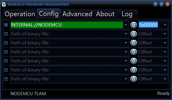
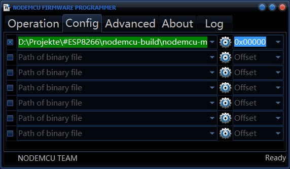
Now you can start the nodemcu-flasher. By default, it will flash an integrated NodeMCU firmware, which can be outdated. Go to the “Config”-tab to select the new firmware you just created in the step before.
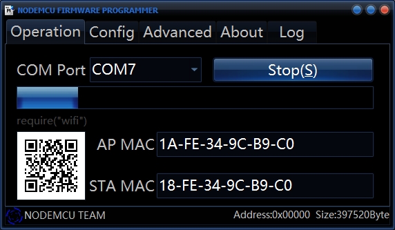
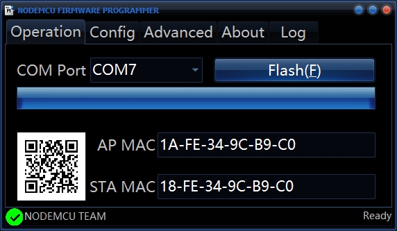
Go to the “Operation”-tab and press the “Flash (F)” button to start the flash operation. The AP MAC and STA MAC should display correct values. If not and the progress bar don’t move, turn your module off and on again to enable flash mode. In flash mode wait until the progress bar is completely filled.
Check your firmware
After flashing we need to check if the firmware is working. Turn off your ESP-01 module and remove GPIO0 from ground then power it on again. Connect with a terminal software to the serial interface which connects to your module. The baud rate has to be 9600.
For testing purpose I connected a red LED and a 470Ohm resistor in series to ground on GPIO2. In your terminal software you set GPIO2 to an output.
The GPIO2 has the IO pin defined to 4!
Your terminal should show something like this:
1
2
3
4
5
6
7
8
9
10
NodeMCU custom build by frightanic.com
branch: master
commit: c8037568571edb5c568c2f8231e4f8ce0683b883
SSL: false
modules: node,file,gpio,wifi,net,tmr,uart
build built on: 2016-01-24 10:52
powered by Lua 5.1.4 on SDK 1.4.0
lua: cannot open init.lua

>
You can now toggle the LED via the console.
1
2
3
gpio.mode(4, gpio.OUTPUT) -- GPIO set to OUTPUT
gpio.write(4, 1) -- GPIO set to HIGH
gpio.write(4, 0) -- GPIO set to LOW
If you can control the LED with these commands, congratulations, your NodeMCU firmware works.