Backlight for a wall clock
I’m wearing glasses during the day, to improve my eyesight. But when I’m in bed, and it is dark, I have trouble to see my clock. Because I have a really nice looking wall clock made out of glass, there is a possibility to illuminate the back of it. The backlight should be switchable via a remote.
Parts for the backlight controller
I only use parts for the backlight I have already lying around, to keep the price of this project low.
- White LED (5mm)
- Constant current source
- Atmel AVR
- Relay
- IRLR024N D-PAK N-Channel FET
- TSOP1738
- LM7805
- old notebook supply (18V)
After some tests with a relay, I skipped this plan. The relay is drawing 150 mA which significantly heats the LDO. So, I will use a FET as a switch to decrease the power dissipation.
RC-5 Protocol
As a remote, I’m using one from my Sony Blu-ray player (remote type RMT-B109P). There is a nice, big key in the middle which can be reached easily.
Sony uses his own protocol for their remotes called SIRC. A command begins with a start bit followed by 7 command bits and 12 to 20 address bits.
High and Low level is defined by the pulse width. The following pulse widths exist:
1
2
3
start bit - length: 3000 µs (2400 µs High; 600 µs Low)
logic 0   - length: 1200 µs (600 µs High; 600 µs Low)
logic 1   - length: 1800 µs (1200 µ High; 600 µs Low)
The commands will be repeated 2 to 3 times. Between the repetition, there is a 45 ms pause.
To find the SIRC code for my specific key, I supplied a voltage to the TSOP1738 and hooked the output signal to my oscilloscope. With the cursor, I can walk through the bits and write down the level. The code of my key looks like this:
1
2
3
Startbit;101.1110;0.1011.0100.0111;
        | Befehl | Adresse        |
        | 0x5E   | 0x0B47         |
I’m only interested in the command because my other remotes are not infrared types. So, I don’t need to distinguish between different remotes with the address.
Writing the code
The signal processing of the TSOP1738 output will be done with an Atmel Atmega8. We use the Input Capture function of the timer for this. At a falling edge, we set our counter variable to 0. When we trigger on a falling edge again, we save the current counter variable, which corresponds to the passed time. With this time we can decide if we have received the start bit, a logical 0 or a logical 1. We use the falling edge because the TSOP1738 outputs an inverted signal.
To initialize the timer on the microcontroller we use the following code:
1
2
3
4
5
6
7
8
9
10
11
12
// Initialize Timer1
void InitTimer1()
{
  // Falling edge detection | clk/64= 4µs
  TCCR1B |= ((1 << CS11) | (1 << CS10));

    // Input Capture Interrupt enable
    TIMSK |= (1 << TICIE1);

    // Configure input for TSOP1738 signal
    RC5_DDR &= ~(1 << RC5_IN);
}
And here is the interrupt function:
1
2
3
4
5
6
7
8
9
10
11
12
13
14
15
16
17
18
19
20
21
22
23
24
25
26
27
28
29
30
31
32
33
34
35
36
37
38
39
40
41
42
// Calculate time between two falling edges in the interrupt
ISR(TIMER1_CAPT_vect)
{
  // Set counter to zero (TCNT1 is now in ICR1)
  TCNT1 = 0;

  // Read the Input Capture Registers
  ICRValue = ICR1;

  // go through the bits
  if (CmdDone == 0 && CmdMatch != 1)
  {
    // Wait until startbit detected
    if (StartBit == 0)
    {
      if (ICRValue > 740 && ICRValue < 760)
      {
        StartBit = 1;
      }
    }
    // If startbit is detected, sample new command
    else
    {
      // If time between two falling edges is 1800µs (range: 1760us - 1840us)
      if (ICRValue > 440 && ICRValue < 460)
      {
        // Set bit at this position to 1
        RC5_cmd_val |= (1 << --CmdBitNumber);
      }
      else
      {
        // CmdBitNumber minus 1 -> bit at this position stays 0
        CmdBitNumber--;
      }
      // If 7 bits are sampled, set CmdDone to 1
      if (CmdBitNumber == 0)
      {
        CmdDone = 1;
      }
    }
  }
}
This function waits for the start bit so it will not start sampling in the middle of a command.
If the start bit is detected the routine will sample the next 7 bits because we only want the command and not the address.
If the routine is done we tell our main function that we have sampled a new command with the CmdDone variable.
Now the main function checks if the command is the one we want to switch the LED on or not.
After the check, it sets CmdDone back to 0 so we can sample a new command.
If the main function detects the required command we switch the LED on, start a second timer and set CmdMatch to 1.
The later will prevent the sampling of a new command during the time the LED are on.
The second timer will turn the LED off after 5 seconds and sets all variables to their default state.
You can find the full source code on GitHub RC5ControlledClocklight (GitHub)
Backlight controller PCB
This is the current schematic in Eagle:
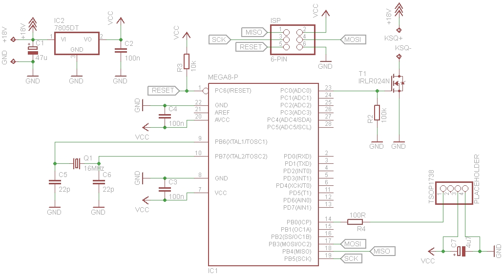
And the current PCB layout looks like this:
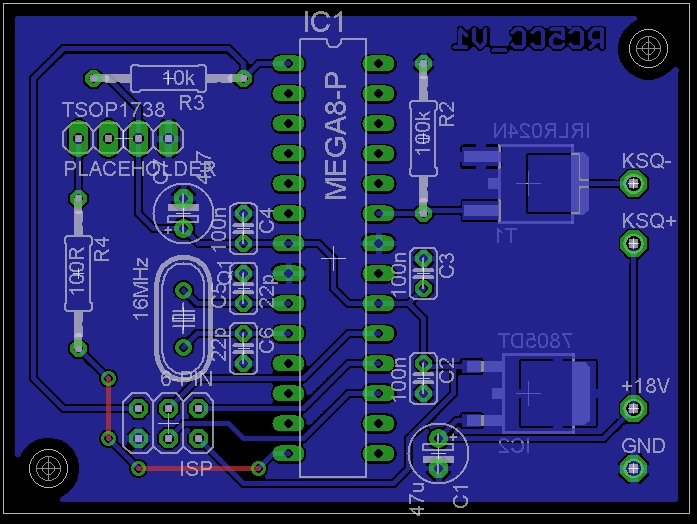
We will create a single layer PCB. So both connections on the top layer will be simple wire jumpers. Always have some holes on your PCB for a mounting option. Here we will use M3 stand-off glued into the case to mount the PCB.
Always check your footprints before you order your PCB. This can be done when you create the part in your ECAD library, or after you have done your layout. I print the whole layout as a 1:1 scale and place the real part on the print. This has saved me multiple times and also this time, I found two issues. The package of the FET and voltage regulator are not matching with the parts I have at home.

So I rotate the voltage regulator 90 degrees to have a little bit more space and change the footprint of both parts.
And this is what the new layout looks like:
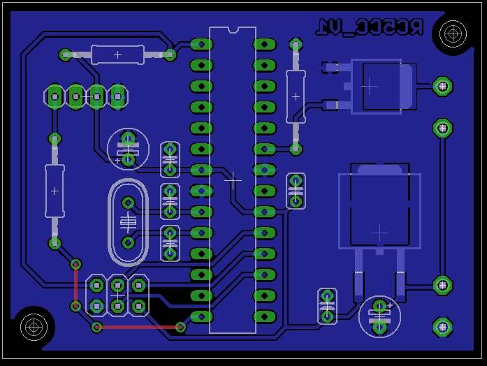
Now that all parts fit on the layout, we can give the layout to the manufacturer. The ground pad on the 7805 is a bit smaller than it should be, but that should be no problem here. With the thermals on the pad, we should be able to solder the pad easily.
Wall clock
The wall clock has to prepared with an LED ring as the backlight. Because there is a black colored circle in the middle, we can hide the LED ring and all the cables behind it. For the LED ring I drew a circle on a piece of paper and marked the LED position every 30 degrees. This results in 12 LEDs on the ring. Tape the LEDs on their position and solder 6 LEDs in series with the help of some silver wire. Do this twice so you have two string of 6 LEDs. I soldered little loops to the silver wire, so I have some more material for gluing it to the glass with hot glue.
I’m using a constant current source for supplying the LEDs. Both strings are attached in parallel to the current source. At 18 V coming from the power supply, we don’t reach the full brightness of the LEDs. If we used three strings of 4 LEDs the constant current source wouldn’t be sufficient. For now, this is as good as it needs to be. In a dark room, I don’t need the full brightness on the backlight anyway.
And this is how it looks on the backside of the clock:

Full source code
1
2
3
4
5
6
7
8
9
10
11
12
13
14
15
16
17
18
19
20
21
22
23
24
25
26
27
28
29
30
31
32
33
34
35
36
37
38
39
40
41
42
43
44
45
46
47
48
49
50
51
52
53
54
55
56
57
58
59
60
61
62
63
64
65
66
67
68
69
70
71
72
73
74
75
76
77
78
79
80
81
82
83
84
85
86
87
88
89
90
91
92
93
94
95
96
97
98
99
100
101
102
103
104
105
106
107
108
109
110
111
112
113
114
115
116
117
118
119
120
121
122
123
124
125
126
127
128
129
130
131
132
133
134
135
136
137
138
139
140
141
142
143
144
145
146
147
148
149
150
151
152
153
154
155
156
157
158
159
160
161
162
163
164
165
166
167
168
169
170
171
172
173
174
175
176
177
178
179
180
181
182
183
184
185
186
187
188
189
190
191
192
193
194
195
196
197
198
199
200
201
202
203
204
205
206
207
208
/*
 * RC5ControlledClocklight.cpp
 *
 * Created: 07.11.2012 19:09:32
 * Author: cronJ
 * Description:	Turn on an LED ring behind a clock, with an IR remote.
 *	Measure time between two falling edges:
 *
 *	3000us => startbit
 *	1800us => logical 1
 *	1200us => logical 0
 *	45ms   => break between the command and the repeat of the command
 *
 *	Actually, only the command is compared. The address from the remote is not compared (maybe soon).
 *	Sony SIRCS code!
 *	Atmel ATmega8
 */

// Includes
#include <avr/io.h>
#include <avr/interrupt.h>
#include <avr/sleep.h>

// Command to be compared
#define RC5_CMD 0x5E

// Signal from TSOP1738 connected to PB0
#define RC5_DDR DDRB
#define RC5_PORT PORTB
#define RC5_IN PB0

// Output to switch LEDs on at PC0
#define LED_DDR DDRC
#define LED_PORT PORTC
#define LED_OUT PC0

// Prototypes
void InitTimer1();
void InitTimer0();
void StartTimer0();
void StopTimer0();

// Interrupt
ISR(TIMER1_CAPT_vect);
ISR(TIMER0_OVF_vect);

// Variables
volatile uint16_t ICRValue;

volatile uint8_t RC5_cmd_val = 0x00;

volatile uint8_t CmdBitNumber = 7;
volatile uint8_t StartBit = 0;

volatile uint8_t CmdDone = 0;
volatile uint8_t CmdMatch = 0;

volatile uint32_t TimerValue = 0;

// Start program
int main(void)
{
	// Timer initialize
	InitTimer1();
	InitTimer0();

	// Set LED pin to output
	LED_DDR = (1 << LED_OUT);

	// Enable interrupts
	sei();

	while(1)
	{
		// Sleep Mode
		set_sleep_mode(SLEEP_MODE_IDLE);
		sleep_mode();

		// If command exists ... compare
		if (CmdDone == 1)
		{
			// If matches required command
			if (RC5_cmd_val == RC5_CMD)
			{
				// Sleep disablen
				//sleep_disable();

				// Set output to 1
				LED_PORT |= (1 << LED_OUT);
				// Set CmdMatch to 1 ... no new command will be sampled
				CmdMatch = 1;
				// Set TimerValue to zero
				TimerValue = 0;
				// Start counting
				StartTimer0();
			}

			// Reset all values
			RC5_cmd_val = 0x00;
			CmdBitNumber = 7;
			StartBit = 0;
			CmdDone = 0;
		}
	}
}

// Calculate time between two falling edges in the interrupt
ISR(TIMER1_CAPT_vect)
{
	// Set counter to zero (TCNT1 is now in ICR1)
	TCNT1 = 0;

	// Read the Input Capture Registers
	ICRValue = ICR1;

	// go through the bits
	if (CmdDone == 0 && CmdMatch != 1)
	{
		// Wait until startbit detected
		if (StartBit == 0)
		{
			if (ICRValue > 740 && ICRValue < 760)
			{
				StartBit = 1;
			}
		}
		// If startbit is detected, sample new command
		else
		{
			// If time between two falling edges is 1800µs (range: 1760us - 1840us)
			if (ICRValue > 440 && ICRValue < 460)
			{
				// Set bit at this position to 1
				RC5_cmd_val |= (1 << --CmdBitNumber);
			}
			else
			{
				// CmdBitNumber minus 1 -> bit at this position stays 0
				CmdBitNumber--;
			}
			// If 7 bits are sampled, set CmdDone to 1
			if (CmdBitNumber == 0)
			{
				CmdDone = 1;
			}
		}
	}
}

// Turn the LED output off after 5 seconds. Reset Timer1 values
ISR(TIMER0_OVF_vect)
{
	TimerValue++;

	//LED_PORT |= (1 << LED_OUT);

	if (TimerValue == 39063) // 256 * 500ns * 39063 = 5,000064s
	{
		// Toggle LED output off
		LED_PORT &= ~(1 << LED_OUT);

		// Stop Timer0
		StopTimer0();

		// Reset values
		RC5_cmd_val = 0x00;
		CmdBitNumber = 7;
		StartBit = 0;
		CmdDone = 0;
		CmdMatch = 0;

		// Sleep mode
		//sleep_enable();
		//sleep_cpu();
	}
}

// Initialize Timer1
void InitTimer1()
{
	// Falling edge detection | clk/64= 4µs
	TCCR1B |= ((1 << CS11) | (1 << CS10));

	// Input Capture Interrupt enable
	TIMSK |= (1 << TICIE1);

	// Configure input for TSOP1738 signal
	RC5_DDR &= ~(1 << RC5_IN);
}

// Initialize Timer0 for the LED output
void InitTimer0()
{
	// Overflow Interrupt Enable
	TIMSK |= (1 << TOIE0);
}

void StartTimer0()
{
	// Clk/8 => 2MHz = 500ns
	TCCR0 |= (1 << CS01);
}

void StopTimer0()
{
	// Deactivate Timer0
	TCCR0 &= ~(1 << CS01);
}